Circular curve
Open a new file, circle.geo, and insert the following code:
DefineConstant[
  R = {1, Min 0.5, Max 10, Step 0.1, Name "R"},
  h = {0.1, Min 0.01, Max 10, Step 0.01, Name "h"}
];
xc = 0;
yc = 0;
Point(1) = {xc, yc, 0, h};
Point(2) = {xc + R, yc, 0, h};
Point(3) = {xc, yc + R, 0, h};
Point(4) = {xc - R, yc, 0, h};
Point(5) = {xc, yc - R, 0, h};
Circle(1) = {2,1,3};
Circle(2) = {3,1,4};
Circle(3) = {4,1,5};
Circle(4) = {5,1,2};
Curve Loop(1) = {1,2,3,4};   // Boundary
Plane Surface(1) = {1};     // Surface
Physical Surface(1) = {1};  // Physical Tag
GMSH should display a circle and a menu on the left with 2 parameters that can be modified on runtime :
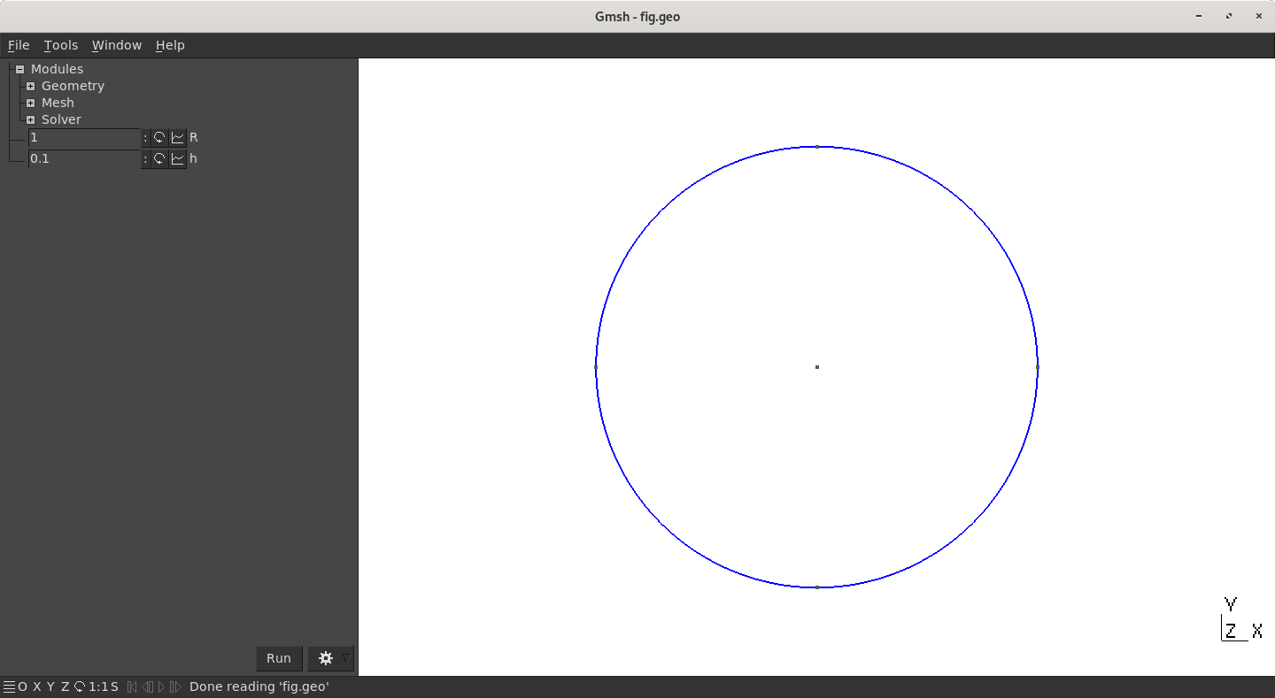
What is defined in DefineConstant is explained in the section dedicated to the GUI (Graphical User Interface) but basically, these lines add parameters that can be modified by the user in the GUI.
What is interesting here is the Circle commands that draws an arc (with angle less than π). It needs three Point to be fully defined (start, center, end):
Circle(index) = {PointA, PointCenter, PointB};
Note that drawing a circle needs 3 points at minimum (instead of 4).
Circle can not draw arc with angle equal or greater than π.
Circle and Line share the same index counter: a Line and a Circle cannot share the same index!
Time to play:
- Introduce a circle of center point (0,0) and of radius
Rintthat can be modified in the GUI, with minimum value 0.1, maximum value 0.4 and aStepof 0.1. You can copy/paste the line whereRis defined and modify it accordingly. - Modify the definition of the
Surfaceto make it looks like a donut instead of a disk

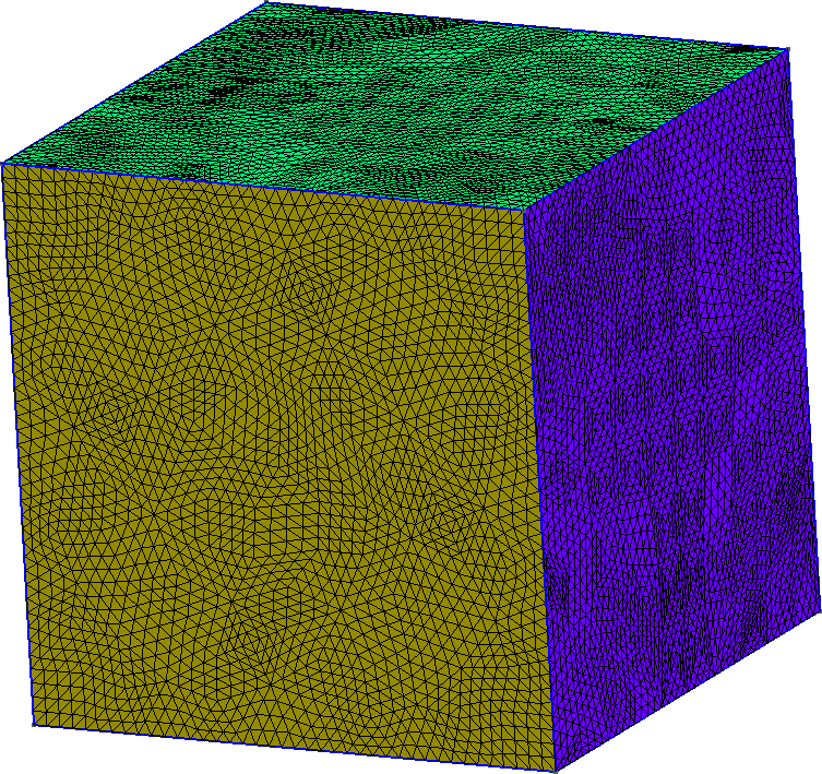
Extrude: from a square to a cube
Extrusion is a nice way to build 3D geometries from 2D:
    h = 1;                     // Characteristic length of a mesh element
    Point(1) = {0, 0, 0, h};   // Point construction
    Point(2) = {10, 0, 0, h};
    Point(3) = {10, 10, 0, h};
    Point(4) = {0, 10, 0, h};
    Line(1) = {1,2};            //Lines
    Line(2) = {2,3};
    Line(3) = {3,4};
    Line(4) = {4,1};
    Curve Loop(1) = {1,2,3,4};   // A Boundary
    Plane Surface(1) = {1};     // A Surface

    Extrude {0, 0, 10} { Surface{1};}  // Extrusion!
    Physical Volume(1) = {1};          // Setting a label to the Volume
The square of width 10 ({ Surface{1};}) is extruded (Extrude) in the z-direction with length 10 ({0, 0, 10}). Applying this code in GMSH gives the following figure: