A square
Let’s go
-
Copy/paste the following code in a new file, named e.g.
square.geo:h = 1; // Characteristic length of a mesh element Point(1) = {0, 0, 0, h}; // Point construction Point(2) = {10, 0, 0, h}; Point(3) = {10, 10, 0, h}; Point(4) = {0, 10, 0, h}; Line(1) = {1,2}; //Lines Line(2) = {2,3}; Line(3) = {3,4}; Line(4) = {4,1}; Curve Loop(1) = {1,2,3,4}; // A Boundary Plane Surface(1) = {1}; // A Surface Physical Surface(1) = {1}; // Setting a label to the Surface -
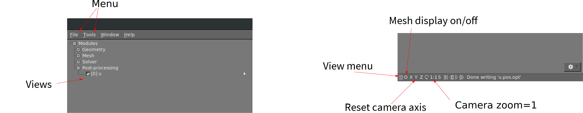
In GMSH, go to
files->open(CTRL+o) and open the file, or typegmsh square.geoin a terminal (warning: this open a new instance of GMSH (which is very light by the way!)). -
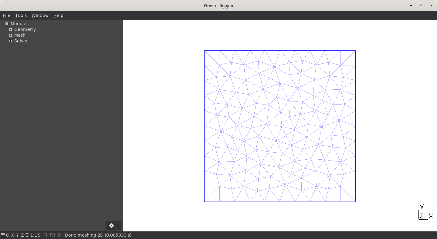
A square should have appear in GMSH’s windows. The camera can be adjusted using the mouse: rotating (
left click), translating (right click) or zooming (wheel). At bottom left of GMSH’s windows, camera can be reseted usingX,Y,Zand1:1(scale) buttons. -
The square can now be meshed by typing
2on the keyboard (or maybeshift+2) or using the menu:Mesh->2D
Log
GMSH is provided with a log console that can be displayed by clicking on the bottom banner of the window. For the square example, you should have something like
Info    : Reading 'square.geo'...
Info    : Done reading 'square.geo'
Info    : Finalized high order topology of periodic connections
Info    : Meshing 1D...
Info    : Meshing curve 1 (Line)
Info    : Meshing curve 2 (Line)
Info    : Meshing curve 3 (Line)
Info    : Meshing curve 4 (Line)
Info    : Done meshing 1D (0.000981 s)
Info    : Meshing 2D...
Info    : Meshing surface 1 (Plane, Delaunay)
Info    : Done meshing 2D (0.017519 s)
Info    : 142 vertices 286 elements
This shows that GMSH starts by meshing the four lines (Meshing 1D...) then the surface. In this example, 142 vertices have been created for a total of 286 elements (lines and triangles).
CTRL + Shift + s or using graphical interface (file->save mesh). By default, the extension of the mesh is .msh and of the same root as the .geo file (i.e. square.geo leads to square.msh).
Code analyse
Parameter h
On the first line of our code is defined a variable, h, which is the characteristic length of the elements.
This size is precised at each Point elementary entity.
Let us play with it (check the tips bellow first):
- Modify the parameter
h, remesh and observe the result - Anisotropic mesh: change only the mesh size of
Point(2), for example withh/10. Remesh and observe the result
0 (zero) (or maybe shift + 0). This forces GMSH to reset and re-read the current file.
Point entity
In GMSH, a volume (3D) is defined by its surfaces, a surface (2D) by its (closed) curves and a curve (1D) by its endpoints. Each of these, Volume, Surface, Curve and Point are named elementary entities in GMSH. The first one that is studied here are the 0D entity: Point. They are defined as follows
Point(index) = {x, y, z, h};
where the parameters are:
index: unique identifier (int> 0) of thePoint. This number has to be set by the user, either manually or usingnewpwhich returns the next available index forPoint(newp= NEW Point).x,y,z: cartesian coordinate of thePointh: mesh element size around thePoint
Apply the following change to square.geo:
- Move some
Pointto obtain a rectangle (instead of a square) - Move some
Pointto get a quadrangle not rectangular at all
Line and Curve Loop entities
Line
It is an oriented segment linking two Point:
Line(index) = {PointA, PointB};
Avec comme paramètres :
index: unique identifier (int> 0) of theLine. As forPoint,this number has to be set by the user, either manually or usingnewl(next available index forLine).PointA: index of the startingPointPointB: index of the endingPoint
Line is oriented!
Curve Loop
Closed loop of Curve (Line being a Curve) that represent a boundary (for a Surface generally):
Curve Loop(index) = {Curve1, Curve2, ..., CurveN};
Where:
index: Unique identifier (int> 0) of theCurve Loop(newllcan be used)CurveX: index of the XthCurve(orLine). If this quantity is negative (e.g. -10) then theCurveis oriented backwardly.
Let’s do a “L-shape” geometry in a new file L.geo as proposed in the below figure (Set a mesh refinement to h=1). You can copy/paste the previous square.geo file to help yourself.

h=1 !)
Surface entity
A Surface is defined by its boundaries: their Curve Loop (possibly more than one):
Plane Surface(index) = {CurveLoop1, CurveLoop2, ..., CurveLoopN};
index: Unique identifier (int> 0) of theSurface(newscan be used)CurveLoopX: index of the XthCurve Loop. As for theLine, this quantity can be negative (e.g. -10) to backwardly orient aCurve Loop.
Modify the “L-shape” geometry to add a hole inside as on the below figure. You will have to add Point and Line obvsiouly, but also a new Curved Loop. The Surface must then be defined by the 2 loops!

Elementary Entities vs. Physical Entities
The last line of the filesquare.geo is:
Physical Surface(1)={1};
This is particular to GMSH and do not affect the geometry rather than the output mesh file. The command is the same for Volume, Surface, Curve and Point:
Physical Volume/Surface/Line/Point(index) = {entity1, entity2, ..., entityN};
Basically, GMSH can set a unique identifier (index) to a set of entities (to regroup them). This new identifier has nothing to do with the previous one you have defined. The output file do not contain the elementary index but only the physical ones. Moreover, only the entities that have a physical tag are saved to the disk! This is explained in detail later.