To understand more precisely what a Physical tag means and how it’s useful, we must have a look at the output file generated by GMSH. It’s also a good idea to understand (a little) how it works, especially with the format v4.
A simple mesh
Let us recall the short program to design a square in GMSH with juste some changes:
h = 1;                         // Characteristic length of a mesh element
Point(1) = {0, 0, 0, h};       // Point construction
Point(2) = {1, 0, 0, h};
Point(3) = {1, 1, 0, h};
Point(4) = {0, 1, 0, h};
Line(11) = {1,2};              //Lines
Line(12) = {2,3};
Line(13) = {3,4};
Line(14) = {4,1};
Curve Loop(1) = {11,12,13,14}; // A Boundary
Plane Surface(18) = {1};       // A Surface
Physical Surface(42) = {18};   // Setting a label to the Surface
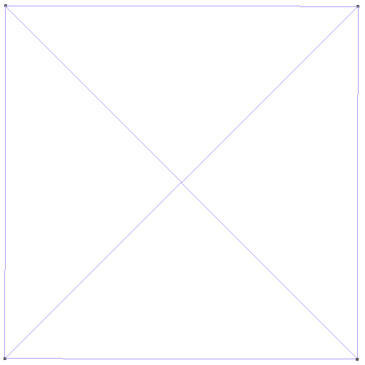
Meshing this geometry leads to a very simple mesh with only 4 triangles and 5 vertices:
Open now the .msh file (not the .geo) and go to Tools→Visiblity, then choose Physical Entities on the bottom dropdown menu:

Tools→Visiblity menu. On the left, Physical entites are shown and on the right, Elementary entities only.
You see that there are only one Physical entity (a surface) and several Elementary entities. You can select one and click enter to display it. For 1D element (segments), you must allows GMSH to show them by checking the box Tools→Options→Mesh→Visibility→1D elements. This menu can also be used to display the tag (Physical or Elementary) directly in the mesh. For example, displaying the Elementary tags leads to this figure
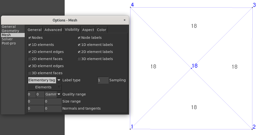
Tools→Options→Mesh→Visibility to select which element types are visible. Elementary tags are shown on the mesh.
and chosing Physical tags to this
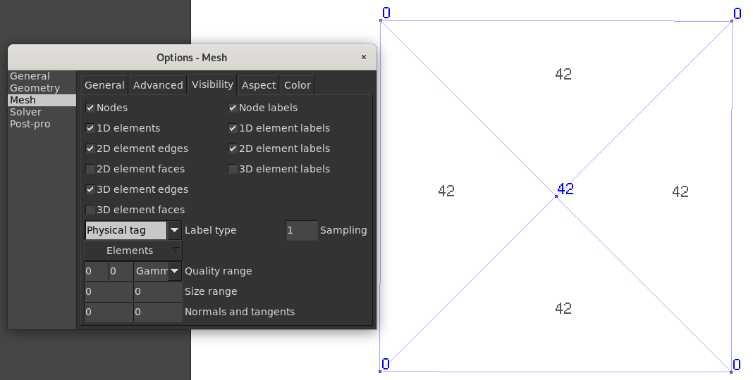
Physical tags are shown on the mesh.
A closer look in the output file
Let us now have a look at the output file (which might differs a bit from yours). It is decomposed into blocks, the first one specifies the msh file format version (here 4.1)
$MeshFormat
4.1 0 8
$EndMeshFormat
The second block contains the elementary entities which is the geometry or the model (not the mesh!). Our square is recognizable in the code, the vertice created in the middle of the square is not stored here (only the 4 corners)
$Entities
4 4 1 0                          // 4 vertices, 4 lines, 1 surface, 0 volume
1 0 0 0 0                        // Vertex n°1, x=0,y=0,z=0, 0 Physical tags
2 1 0 0 0                        // Vertex n°2, x=1,y=0,z=0, 0 Physical tags
3 1 1 0 0                        // Vertex n°3, x=1,y=1,z=0, 0 Physical tags
4 0 1 0 0                        // Vertex n°4, x=0,y=1,z=0, 0 Physical tags
11 0 0 0 1 0 0 0 2 1 -2          // Curve n°11
12 1 0 0 1 1 0 0 2 2 -3          // Curve n°12
13 0 1 0 1 1 0 0 2 3 -4          // Curve n°13
14 0 0 0 0 1 0 0 2 4 -1          // Curve n°14
18 0 0 0 1 1 0 1 42 4 11 12 13 14// Surface n°18 with Physical tag = 42
$EndEntities
The last line defines the surface and if you looking closely, you can see 42 which is the Physical tag we set to the surface. The elementary tags are also saved.
Let us continue to watch the file. The mesh information arrives now, first the nodes (or vertices) are defined:
$Nodes
5 5 1 5 // Global info
0 1 0 1 // Block 1
1        // Node tag 1
0 0 0       //x=0, y=0, z=0
0 2 0 1 // Block 2
2        // Node tag 2
1 0 0       //x=1, y=0, z=0
0 3 0 1 // Block 3
3        // Node tag 3
1 1 0       //x=1, y=1, z=0
0 4 0 1 // Block 4
4        // Node tag 4
0 1 0       //x=0, y=1, z=0
2 18 0 1 // Block 5
5          // Node tag 5
0.5 0.5 0    //x=0.5, y=0.5, z=0
$EndNodes
In the global and block info are stored some information such as, to which elementary entity belongs the nodes. For example node 1 belonds to the elementary entity Point(1) (the geometry) while the node 5 has been created for the mesh and hence belongs to the Surface(18).
The part that interest us is the last one, containing infomation about the elements:
$Elements
1 4 1 4 // 1 block, 4 elements, tag min=1, tag max=4
2 1 2 4 // dim=2, tag=1 (surface), triangle (type=2), 4 elements in block
1 1 2 5 // Triangle n°1 linking vertex 1, vertex 2, vertex 5
2 4 1 5 // ...
3 2 3 5
4 3 4 5
$EndElements
Clearly, the four triangles have been saved here!
Let’s play
Let us have a look on what changes if we add a Physical tag to a line. For example, let now add this to the end of the .geo file:
Physical Curve(98) = {11}; // set physical tag 98 to Curve (=line) 1
Mesh it and read the file again. The only difference should appears, first on line 10, when Line(11) is defined because now, it has a Physical tag (98):
11 0 0 0 1 0 0 1 98 2 1 -2
Second, in the $Elements parts, now the 2 mesh segments that belongs to the Line(11) are stored as element line!
$Elements
2 5 1 5  // 2 blocks, 5 elements, tag min=1, tag max=5
1 11 1 1 // The line mesh, elementary tag = 11, elements = segment (type =1), 1 elements
1 1 2      // The segment joining nodes 1 to 2
2 18 2 4 // The surface mesh, elementary tag = 18, elements = triangle (type =2), 4 elements
2 1 2 5    // triangle 2 ...
3 4 1 5
4 2 3 5
5 3 4 5
$EndElements
What if no Physical entity is defined?
Then every mesh elements, even vertices, are stored. For example, it would give this file
$Elements
9 12 1 12
0 1 15 1  // Point (dim = 0)
1 1         // element 1 is linking to Point(1)
0 2 15 1
2 2
0 3 15 1
3 3
0 4 15 1
4 4
1 11 1 1 // Line(11)
5 1 2      //its segment mesh (element)
1 12 1 1
6 2 3
1 13 1 1
7 3 4
1 14 1 1
8 4 1
2 18 2 4 // Surface(18)
9 1 2 5    //triangle ...
10 4 1 5
11 2 3 5
12 3 4 5
$EndElements
Take away messages
- Every vertices and every elementary entities are saved in the mesh file, whatever the
Physicaltags… - … But only the mesh elements (line, triangle, …) belonging to an elementary entity with a
Physicaltag will be saved! - If no
Physicalentity is defined then everything is saved (which is probably too much!)
Physical Tag on these boundaries. Otherwise, the boundary elements will not exist!
Physical tags to keep control on the output result. It’s also recommended to define the Physical Entities at the end of the .geo file only: OpenCascade might delete or change the numbering of elementary entities!
Other file format
Other mesh formats are available, such as MATLAB or VTK (ParaView) and converters are available in the source code of GMSH for example for Python.
Last but not least, GMSH file format version 4 is quite new and the previous one, format version 2 was quite easier to understand. This new format can however manages more complex situation such as automatic partitioning or ghost cells.