Geometries
Example of a Box
Open a new file, box.geo, and copy/paste the following line on top of the file:
SetFactory("OpenCASCADE");
This command forces GMSH to use OpenCascade engine instead of the native one.
With this engine, you generally do not have to build the Point by hand, as ready-to-use geometries are provided. The mesh size must however still be set on every Point. A handy way to set the same mesh size to every Point is to use the two commands Mesh.CharacteristicLengthMin and Mesh.CharacteristicLengthMax at the beginning of the file :
SetFactory("OpenCASCADE");

h = 0.1; // or whatever
Mesh.CharacteristicLengthMin = h;
Mesh.CharacteristicLengthMax = h;
Now, we are going to build the box. Instead of creating the Point, Line, Surface and finally the Volume, add the following line to the file
Box(1) = {0, 0, 0, 1, 1, 1};
And here you go (⌐■_■) ! A nice box of size 1 in every direction (e.g a cube), in a single line!
The Box commands have the following syntax:
Box(index) = {x, y, z, lx, ly, lz};
where
index: unique identifier of the resulting elementaryVolumex,y,z: cartesian coordinates of the “bottom left” pointlx,ly,lz: size in the (resp.) x-,y- and z- direction of the box
Time to play!
- Build a box with
lx= 1,ly= 0.5 andlz= 0.75 - Mesh in 2D
Tools→Option→Mesh then select a value (e.g 50) at Normals (bottom left).
Some available geometries
| Dim. | Name and syntax | Description |
|---|---|---|
| 2D | Disk(index)= {x,y,z,R} |
Disk of radius R and center (x,y,z) |
| 2D | Rectangle(index)= {x,y,z,lx,ly} |
Rectangle in the (x,y) plan which the “bottom left” point is located at (x,y,z). The rectangle sizes are lx and ly in the x- and y-direction respectively |
| 3D | Sphere(index)= {x,y,z,R} |
Sphere of radius R and of center (x,y,z) |
| 3D | Cylinder(index)= {x,y,z, xv, yv, zv, R, alpha} |
Cylinder of radius R build from a circule of center (x,y,z), extruded along the vector (xv,yv,zv) . Optional parameter alpha represents angular opening of the Cylinder (for partial disk) |
| 3D | Torus(index)= {x,y,z,R1, R2} |
Torus of radii R1 and R2 and of center (x,y,z) |
| 3D | Cone(index)= {x,y,z, dx,dy,dz,R1, R2} |
Cone of center (x,y,z) , of direction (dx,dy,dz) and of radii R1 and R2 (which can be zero!) |
Boolean operations: CAD like a boss (⌐■_■)
General Syntax
Four boolean operations are available in GMSH. They all need two input arguments: an object (first argument) and a tool (second argument). The index of the created element can be provided by the user but remember that the result can be “different” from what expected: a boolean operation can create multiple entities and hence, applying a single index does not make sense!
//Two possible syntax (beware the ";")
BooleanOperation{Object_List; Delete; }{Tool_List; Delete;}
BooleanOperation(index) = {Object_List; Delete; }{Tool_List; Delete;} ;
The Object_List and Tool_List are not list in the programming point of view rather that an enumeration of entities (Point, Line, Surface, Volume). For example, the list of Line numbered 2, 3 and 6, Surface of every number from 42 to 50 and Volume 11 and 15 will be written as:
Line{2,3,6}; Surface{42:50}; Volume{11,15};
Delete; is optional but generally recommended and forces GMSH to delete the entities passed as argument (both the tool and the object). Otherwise, there is a high risk of getting dupplicated entites!
The 4 operations
| Name and syntax | Description |
|---|---|
BooleanIntersection |
Intersection between the objet et l’outil |
BooleanUnion |
Union between the object and the tool |
BooleanDifference |
Substracting the tool to the object |
BooleanFragments |
Compute each fragments resulting from the intersection of the entities of the object and of the tool. This command moreover delete any dupplicated entities and make every interface |
BooleanFragments is probably the most usefull and powerful operation.
Example: it’s a good day to dice
Code and expectation
There is nothing better as an example to understand a tool. Let’s build a 6-faces dice in a dice.geo file (copy/paste the following code):
SetFactory('OpenCASCADE');
Mesh.CharacteristicLengthMax = 0.1;
Mesh.CharacteristicLengthMin = 0.1;
Box(1) = {-0.5,-0.5,-0.5, 1, 1, 1};
Sphere(2) = {0,0,0, 0.65};
BooleanIntersection{ Volume{1}; Delete;}{ Volume{2}; Delete;}
Analyse of the code
First, the OpenCascade is set (line 1), then the cube is created (Box) and a sphere (Sphere). The associated Volume indices are respectively 1 and 2. Finally, the boolean operation is launch
BooleanIntersection{ Volume{1}; Delete;}{ Volume{2}; Delete;}
The intersection between Volume{1} (the cube) and Volume{2}(the sphere) is computed. Both Volume are then deleted due to Delete; but GMSH will create a new Volume and the possible Surface and Line associated and, obviously, will provide them a unique identifier. The indices are generally chosen as the “first number available”. As the Volume 1 and 2 has been deleted, there is “high chance” that the index of the newly created Volume will be 1 (because “1” has been freed). This can be check by going in the menu, Tools→Visiblity, and check the elementary entities indices (see remark below).
Line, Surface and Volume indices are modified by the Delete in the boolean operations!
Tools→Visiblity menu (shortcut: ctrl + shift + v). Chose then to display Elementary Entities in the dropdown menu at bottom left.
Delete; command and have a look in the visualisation window (Tools→Visiblity). You should see multiple Volume that overlap each other…
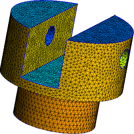
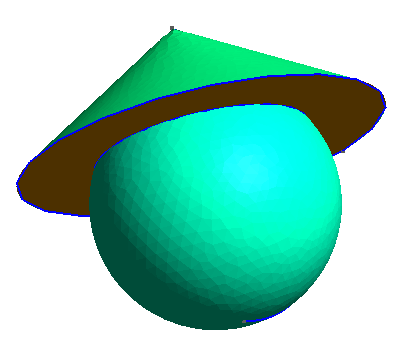
Draw this head with a conical hat as in the following figure. Be sure that, in the end, there is only one Volume.
To help you design this nice geometry: the sphere is centered at (0,0,0) with a radius equal to 1 while the cone is of parameter (0, 0, 0.5, 0, 0, 1, 1.5, 0).
A focus on BooleanFragments
Probably the most usefull but the less intuitive operation, BooleanFragments, does the following two operations:
- Fragment the elementary entities: each intersection between entities are computed and become a newly entity with its own index
- Delete every dupplicated entity, in particular common boundaries (e.g between two
SurfaceorVolume)
Let us take the simple case of a geometry composed by a square and a disk with non empty intersection:
SetFactory("OpenCASCADE");
Mesh.CharacteristicLengthMin = 0.1;
Mesh.CharacteristicLengthMax = 0.1;
Rectangle(1) = {-0.5,-0.5, 0, 1, 1};
Disk(2) = {0.75, 0, 0, 0.75, 0.75};
Mesh 2; // Force GMSH to mesh
Opening this file in GMSH is a deceiving experience: there are 2 meshes and they are overlapping each other!
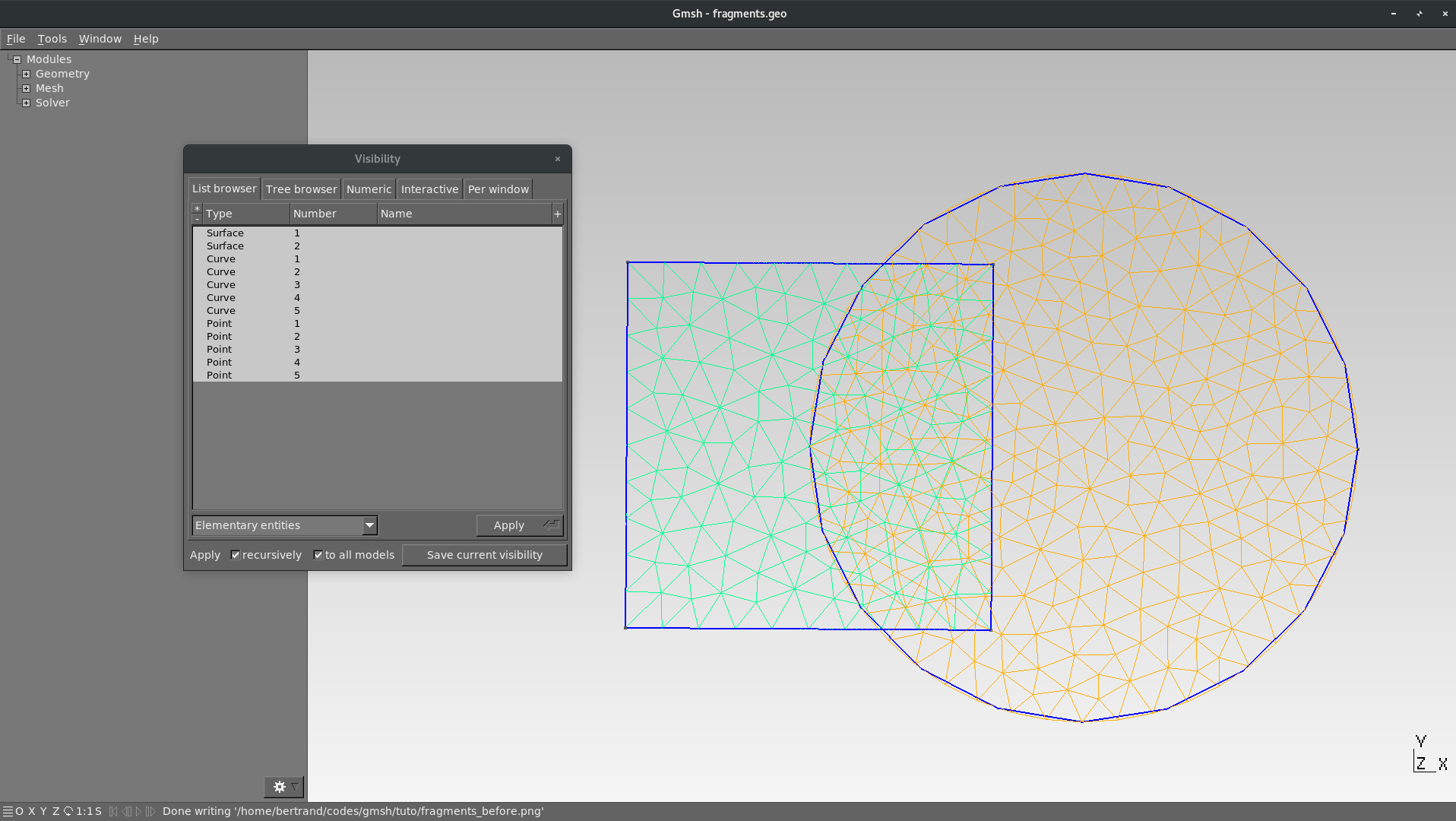
BooleanFragments: overlapping meshes
Let us now add the fragmentation:
SetFactory("OpenCASCADE");
Mesh.CharacteristicLengthMin = 0.1;
Mesh.CharacteristicLengthMax = 0.1;
Rectangle(1) = {-0.5,-0.5, 0, 1, 1};
Disk(2) = {0.75, 0, 0, 0.75, 0.75};
BooleanFragments{ Surface{1,2}; Delete; }{}
Mesh 2; // Force GMSH to mesh
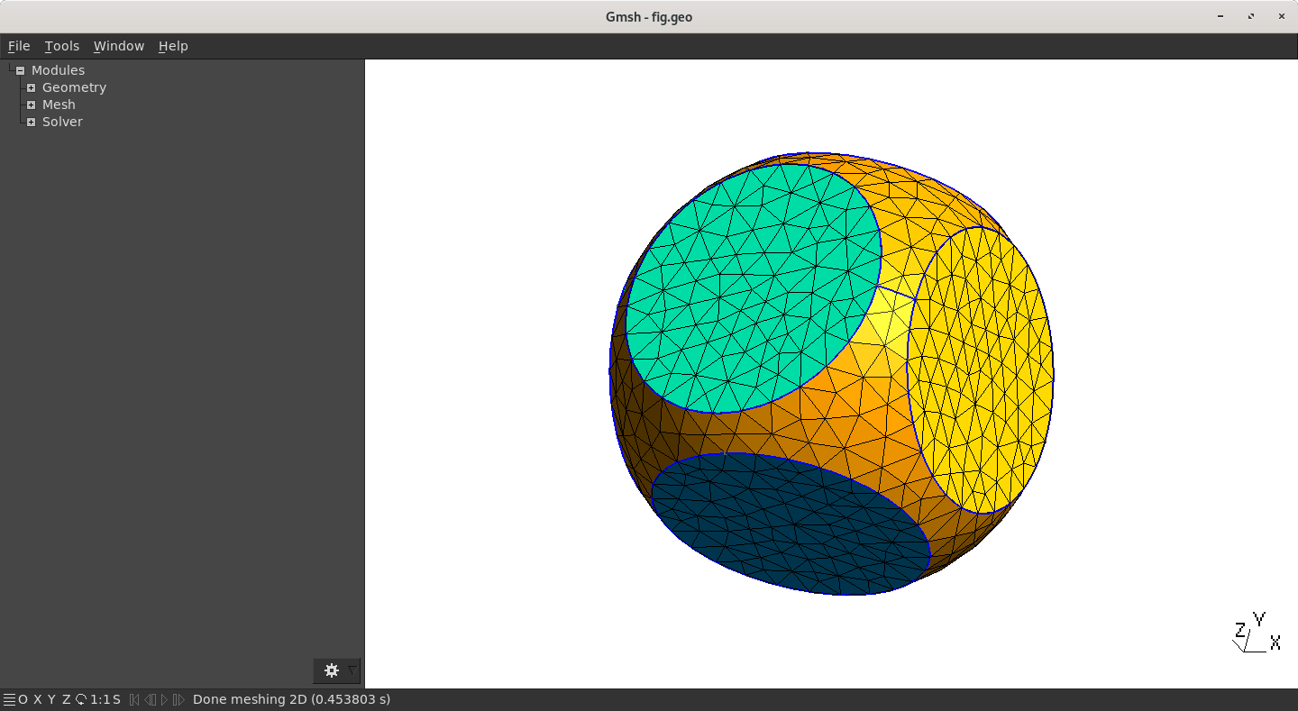
Three entities are created (instead of only one) but there is only one (connected) mesh and no dupplicated boundaries. The three Surface can be regrouped lated into a single Physical Tag so this is absolutely not a problem.
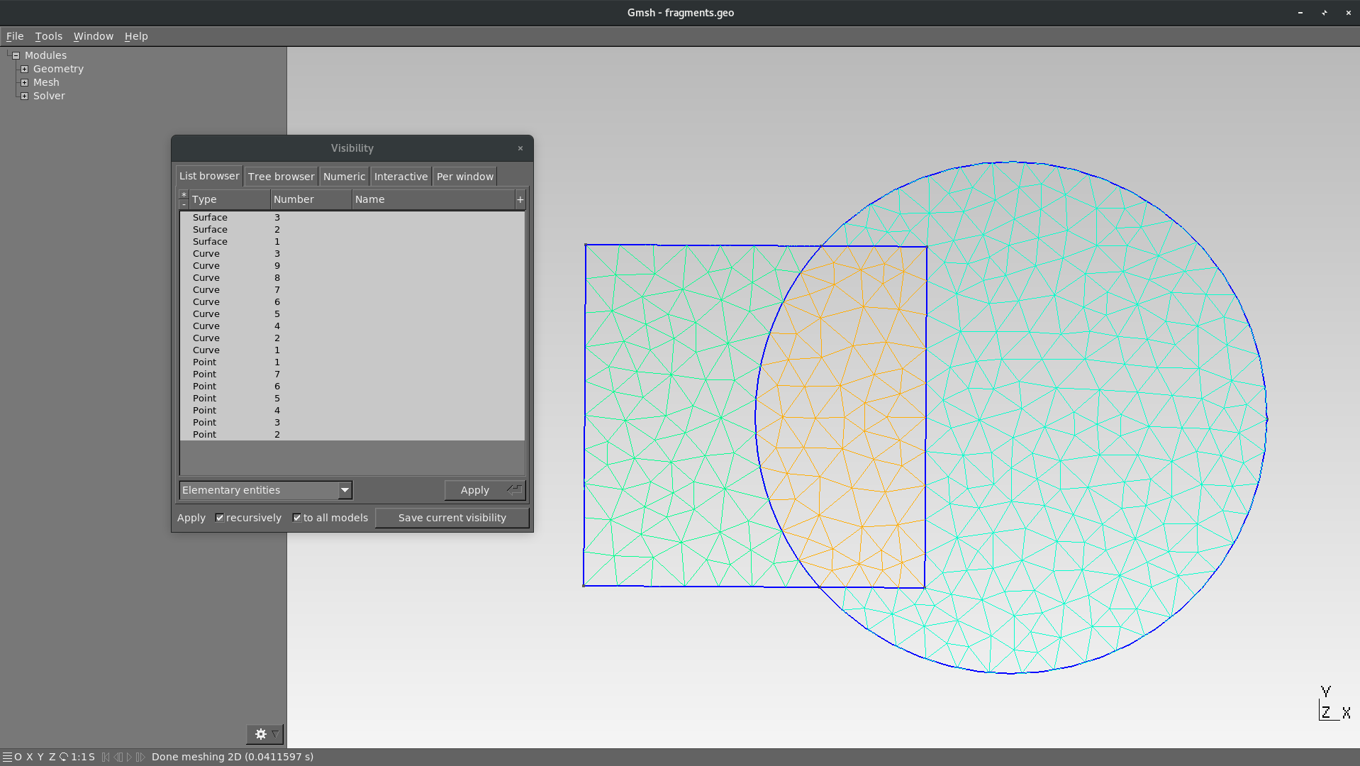
BooleanFragments
BooleanFragments has no really impact on the result. The tool argument can for example be empty as above.
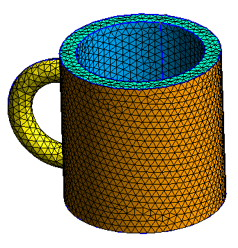
Training examples
Create a nice mug as the below picture. You can use the Rotation operation to rotate the handle:
Rotate{{x,y,z}, {xp,yp,zp}, a}{List}
where (x,y,z) is a vector on the rotation axis, (xp,yp,zp) a point on the axis and a the angle of rotation (in rad). The List argument contains the entities to be modified (Line, Surface and Volume). The quantity π in GMSH is given by the hard coded command Pi.
Try and reproduce the following geometry